'아두이노'에 해당되는 글 7건
- 2015.06.11 컨트롤용 보드용 코드를 짜다.
- 2010.12.09 ArduinoIMU #1. 소스 수정..
- 2010.08.02 아두이노 - 내장 라이브러리 사용 스테핑 모터 구동 소스.
- 2010.08.02 아두이노 - 스테핑 모터 컨트롤러(SLA7062M) 소스
- 2010.07.21 Micro quad - wii copter 만들기 #2 schematic & 준비물
- 2010.07.21 micro qaud - wii copter 를 만들기 시작.#1
- 2010.07.16 아두이노 wmp 소스
컨트롤용 보드용 코드를 짜다.
#include <Wire.h>
#include <EEPROM.h>
#include <pins_arduino.h>
#define MOTOR_1 (3)
#define MOTOR_2 (9)
#define MOTOR_3 (10)
#define MOTOR_4 (11)
//PIN assignment
#define CHANNEL_NUM (3) // use ar7000 satelite receiver - spektrum
#define THROTTLEPIN (2)
#define STEERPIN (4)
#define AUXPIN (5)
#define RECIEVER_SENSITIVITY (10)
#define MOTOR_SENSITIVITY (10)
int16_t rcCommand1 = 0;
int16_t rcCommand2= 0;
int16_t rcCommand3= 0;
int16_t rcCommand4 =0;
uint8_t pinRcChannel[3] = {THROTTLEPIN,STEERPIN,AUXPIN};
uint8_t PCintLast = 0;
// +++++++++++++++++++++++++++++++++++++++++++++++++++++++++++++++++++++++
// main loop
// +++++++++++++++++++++++++++++++++++++++++++++++++++++++++++++++++++++++
uint32_t previousTime = 0;
uint32_t currentTime = 0;
uint32_t deltaTime = 0;
uint32_t meanTime = 0;
uint32_t rcTime = 0;
uint8_t armed = 0;
short commandFilter(short old_val, short new_val)
{
short ret;
ret = constrain(new_val,old_val-RECIEVER_SENSITIVITY,old_val+RECIEVER_SENSITIVITY);
return ret;
}
short MotorFilter(short old_val,short new_val) {
short ret;
ret= constrain(new_val,old_val-MOTOR_SENSITIVITY,old_val+MOTOR_SENSITIVITY);
return ret;
}
typedef struct {
uint16_t edgeTime;
int16_t Width;
} pinTimingData;
pinTimingData pin1;
pinTimingData pin2;
pinTimingData pin3;
pinTimingData pin4;
SIGNAL(PCINT2_vect) {
uint8_t mask;
uint16_t cTime;
uint16_t temp;
cTime = micros();
mask = PIND ^ PCintLast;
PCintLast = PIND;
// mask is pins [D0-D7] that have changed.
// chan = pin sequence of the port. chan begins at D2 and ends at D5
// because we are here, at least one pin [D2-D5] changed
// avoiding a for() is more than twice faster !
if (mask & (1<<THROTTLEPIN)) {
if (!(PIND & 0x01 << THROTTLEPIN)) temp = cTime - pin1.edgeTime;
pin1.Width = (int16_t)(temp - 1120); // minimum throttle
pin1.edgeTime = cTime;
}
if (mask & (1<<STEERPIN)) {
if (!(PIND & 0x01 << STEERPIN)) temp = cTime - pin2.edgeTime;
pin2.Width = (int16_t)(temp - 1500);
pin2.edgeTime = cTime;
}
if (mask & (1<<AUXPIN)) {
if (!(PIND & 0x01 << AUXPIN)) temp = cTime - pin3.edgeTime;
pin3.Width = (int16_t)(temp - 1500);
pin3.edgeTime = cTime;
}
}
// Configure each rc pin for PCINT
void configureReceiver() {
uint8_t chan;
PCMSK2 = 0;
for (chan=0; chan < 4; chan++) {
pinMode(pinRcChannel[chan], INPUT);
// PCINT activated only for specific pin inside [D0-D7] , [D2-D5] for this tricopter
PCMSK2 |= digitalPinToBitMask(pinRcChannel[chan]);
}
PCICR = 0x01 << 2; // PCINT activated only for [D0-D7] port
}
void setup() {
pinMode (13, OUTPUT);
Serial.begin(115200);
delay(100);
configureReceiver();
previousTime= micros();
meanTime = 1500;
digitalWrite(13,HIGH);
}
const long windUp = 1000;
void loop() {
int numc;
short temp1, temp2;
float error;
float dTerm;
float timeFactor;
float invTimeFactor;
float tmp;
rcCommand1 = commandFilter(rcCommand1,pin1.Width);
rcCommand2 = commandFilter(rcCommand2,pin2.Width);
rcCommand3 = commandFilter(rcCommand3,pin3.Width);
rcCommand4 = commandFilter(rcCommand4,pin4.Width);
Serial.print(rcCommand1);
Serial.print(",");
Serial.print(rcCommand2);
Serial.print(",");
Serial.print(rcCommand3);
Serial.print(",");
Serial.print(rcCommand4);
Serial.println();
currentTime = micros();
deltaTime = currentTime - previousTime;
previousTime = currentTime;
meanTime = (39*meanTime + deltaTime)/40;
timeFactor = deltaTime/meanTime;
invTimeFactor = meanTime/deltaTime;
//++++++ motor control ++++++++++++++++++++++++++++++++++
temp1 = rcCommand1;
constrain(temp1,0,255);
analogWrite(MOTOR_1,temp1);
temp1 = rcCommand2;
constrain(temp1,0,255);
analogWrite(MOTOR_2,temp1);
temp1 = rcCommand3;
constrain(temp1,0,255);
analogWrite(MOTOR_3,temp1);
temp1 = rcCommand4;
constrain(temp1,0,255);
analogWrite(MOTOR_4,temp1);
delay(100);
}
ArduinoIMU #1. 소스 수정..
아두이노 - 내장 라이브러리 사용 스테핑 모터 구동 소스.

아두이노 - 스테핑 모터 컨트롤러(SLA7062M) 소스
Micro quad - wii copter 만들기 #2 schematic & 준비물
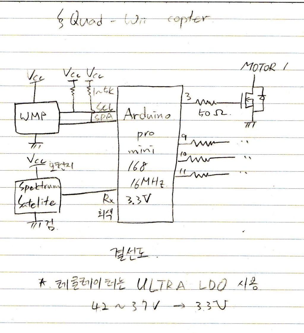
구상한 회로도이다.


